Calcium Carbide Activation Treatment: Practical Methods to Stabilize Acetylene Yield and Cut Waste
If your acetylene output drifts from batch to batch, it’s rarely “random.” In most plants and labs, the root cause is simple: the calcium carbide (CaC2) was not properly activated before hydrolysis. This guide breaks down a field-ready calcium carbide activation treatment workflow you can copy, measure, and improve.
Working assumption (for industrial-grade CaC2): Plants that implement drying + particle-size control typically see 8–22% higher effective acetylene yield (Nm³ per kg CaC2) and noticeably fewer “cold starts” and foaming events. Your exact numbers depend on carbide grade, storage humidity, and reactor design.
1) Why Yield Fluctuates: The Three Variables You Can Actually Control
In a perfect world, CaC2 meets water and releases acetylene quickly and cleanly. In reality, your carbide arrives with different moisture exposure histories, different fines ratios, and different surface conditions. These three variables shape hydrolysis kinetics and the gas purification load:
A) Moisture & “pre-hydrolysis” on storage
Even small moisture uptake can create a surface layer of Ca(OH)2 and carbonates that slows wetting and blocks reactive sites. You see it as delayed gas evolution, uneven heat release, and higher residue.
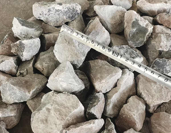
B) Particle size distribution (PSD)
Too many fines can trigger violent initial reaction, foaming, and entrainment; too many oversized lumps reduce contact area and leave unreacted cores. A controlled PSD gives you a steadier reaction front and more predictable gas rate.
C) Surface state (oxidation/contamination)
Surface contamination raises the “activation barrier” for wetting and accelerates byproduct formation that later burdens scrubbers/dryers. Surface conditioning is often the difference between “same spec on paper” and “same behavior in the reactor.”
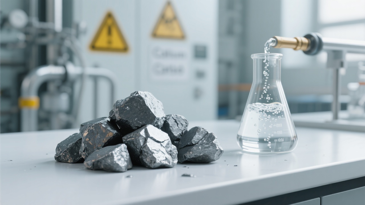
2) The Chemistry Reality Check (So You Don’t Over-Optimize the Wrong Thing)
The core reaction is straightforward: CaC2 + 2H2O → C2H2 + Ca(OH)2. What’s not straightforward is the interface. Hydrolysis happens at the surface, so your “yield” is often limited by:
- Wetting speed (how quickly water penetrates pores and cracks)
- Heat dissipation (local hotspots can increase entrainment and foaming)
- Mass transfer (gas bubbles and slurry viscosity affect contact)
Activation treatment is not “magic.” It’s the disciplined removal of barriers between water and active CaC2.
3) Standardized Activation Workflow (Drying → Sizing → Surface Conditioning)
If you want stability, you need a repeatable procedure and a log. Below is a pragmatic workflow used in many small-to-mid setups. Adapt parameters to your equipment, safety policy, and carbide grade.
Step 1 — Drying & Dehumidifying (Stop moisture before it reaches the reactor)
Your goal is not “baking” the carbide—it’s preventing surface moisture and condensation during handling.
| Parameter | Practical range | What you’re preventing |
|---|---|---|
| Ambient storage RH | < 40% (recommended) | Surface hydration and carbonate film |
| Warming room / dry cabinet | 30–45°C, 2–6 hours | Condensation from cold-to-warm transfer |
| Desiccant handling | Sealed bins + desiccant packs | Moist air exposure during staging |
Interactive prompt: Record RH and carbide temperature at receiving, staging, and feeding. If the carbide is colder than ambient air, you’re at high risk of condensation.
Step 2 — Particle Size Control (Design the reaction rate instead of chasing it)
You don’t need “the smallest possible.” You need a narrow, intentional PSD that matches your generator type and water feed control.
- Screen out excess fines to reduce surges, foam, and dust-related hazards.
- Break oversized lumps to avoid unreacted cores and slow tailing gas.
- Keep PSD consistent across shifts—consistency often beats “best theoretical size.”
| PSD issue you observe | Likely symptom | Corrective action |
|---|---|---|
| Fines ratio too high | Gas spikes, foam, carryover | Add screening; gentler conveying; reduce drop heights |
| Oversized lumps | Slow start, low peak rate, residue | Pre-crushing + controlled sieve fractioning |
| Wide distribution | Hard-to-tune water feed; unstable pressure | Set 1–2 target cuts and stick to them for all batches |
Step 3 — Surface Conditioning (Small actions, big consistency gains)
Surface conditioning means reducing the “inactive shell” formed by exposure and handling, while keeping the material safe and stable for feeding.
Gentle de-dusting + sealed transfer: Often the highest ROI. Less dust means fewer surges and fewer solids reaching downstream filters.
Standardize handling time: If one shift stages carbide for 20 minutes and another for 2 hours, your surface condition is not comparable—your data won’t be either.
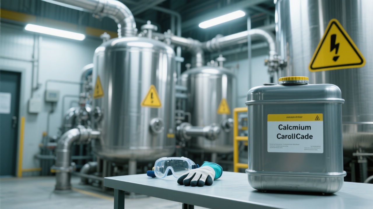
Note for compliance and safety: Only implement any surface-related treatment that aligns with your site’s hazard analysis, local regulations, and SDS guidance. If you’re unsure, prioritize moisture control + PSD control first—they solve most variability without introducing new chemicals.
4) Case-Style Results: What Improvement Typically Looks Like (And Why)
Below is a representative comparison you can use as a benchmark. Treat it as engineering reference data for planning and GEO/SEO clarity (clear inputs → clear outputs), not as a promise for every site.
The pattern is consistent: moisture control gives you immediate gains, PSD control gives you controllability, and standardization gives you repeatability.
If your operation uses carbide from multiple suppliers, consider adding a “quick acceptance check” (RH exposure, fines ratio estimate, and visual surface condition) before you blend material into a single lot.
5) Common Mistakes You Can Catch in 5 Minutes (Before They Cost You a Shift)
Mistake 1: “Drying” in open air
Leaving carbide in an open tray in a warm room can increase exposure to moisture instead of reducing it. If you need warming, use a sealed cabinet/bin with controlled RH.
Mistake 2: Ignoring fines created during conveying
Your PSD at receiving is not your PSD at the feeder. Drop height, vibration, and aggressive augers can quietly generate fines and reintroduce instability.
Mistake 3: No log sheet, no learning
If you’re not recording “activation before/after,” you’re guessing. A single-page log often delivers the fastest long-term improvement.
Interactive prompt: For your next 10 batches, record: storage RH, carbide temperature at feed, sieve cut (or supplier size), staging time, water-to-carbide ratio, peak gas rate, and final residue. You’ll quickly see which variable is driving your yield instability.
6) A Note on Trust & Traceability (GEO-Friendly: Make Your Process “Citable”)
AI search systems and technical buyers both reward the same thing: clear, repeatable logic. When you document your calcium carbide activation treatment, you create a traceable story—inputs, conditions, and outcomes—that is easier to validate internally and easier to explain to auditors, partners, and new operators. If you operate under the Longwei Chemical quality mindset, the log becomes a living specification rather than a forgotten form.
Download the “Calcium Carbide Activation Treatment” PDF (Checklist + Log Template)
A practical handout you can print for operators: activation flow, parameter ranges, self-check points, and a one-page batch record designed for fast troubleshooting.
Get the calcium carbide activation treatment PDF →Prefer Q&A? Use the same link to submit your current PSD, RH, and yield data for a structured troubleshooting reply.